HDMA examples: Difference between revisions
(→HDMA Tables: If Line-Counter is 0x80: count = 128, repeat flag = 0) |
m (→Non-repeat HDMA entries: Fix typos) |
||
| Line 88: | Line 88: | ||
=== Non-repeat HDMA entries === | === Non-repeat HDMA entries === | ||
A non-repeat HDMA entry (bit-7 of ''Line-Counter'' clear or ''Line-Counter'' == <tt>0x80</tt>) is <tt>hdma_transfer_bytes + 1</tt> bytes in size. It | A non-repeat HDMA entry (bit-7 of ''Line-Counter'' clear or ''Line-Counter'' == <tt>0x80</tt>) is <tt>hdma_transfer_bytes + 1</tt> bytes in size. It consists of the ''Line-Counter'' byte, followed by the data to transfer on the next Horizontal Blanking Period. Afterwards, the HDMA controller will wait for ''count'' (bits 0-6 of ''Line-Counter'') scanlines before processing the next HDMA entry. | ||
If the ''Line-Counter'' byte is <tt>0x80</tt>, the HDMA entry is a non-repeating entry that will wait 128 scanlines. | If the ''Line-Counter'' byte is <tt>0x80</tt>, the HDMA entry is a non-repeating entry that will wait 128 scanlines. | ||
| Line 102: | Line 102: | ||
db 0x04 // TM = BG3 | db 0x04 // TM = BG3 | ||
db 1 // 1 scanline | db 1 // 1 scanline, non-repeat entry | ||
db 0x13 // TM = BG1, BG2, OBJ | db 0x13 // TM = BG1, BG2, OBJ | ||
| Line 108: | Line 108: | ||
</pre> | </pre> | ||
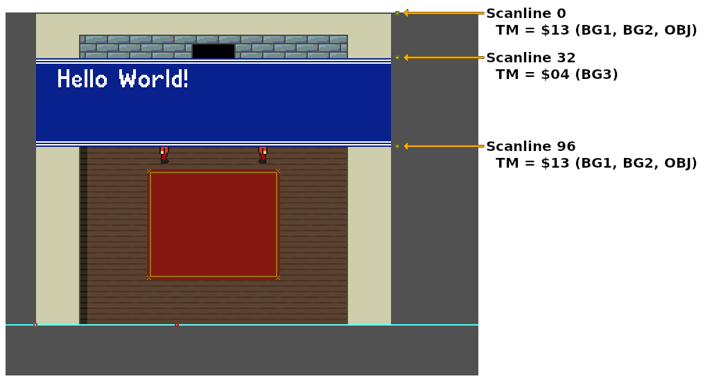
[[File:Hdma_textbox_events.png||Annotated Mesen-S Event Viewer screenshot of a HDMA to the | [[File:Hdma_textbox_events.png||Annotated Mesen-S Event Viewer screenshot of a HDMA to the TM register]] | ||
| Line 137: | Line 137: | ||
dw -6 | dw -6 | ||
db 16 // 16 scanlines | db 16 // 16 scanlines, non-repeat entry | ||
dw -8 | dw -8 | ||
Revision as of 07:26, 25 November 2022
Examples for using HDMA.
Transfer patterns
The following is a suggested list of PPU registers that can be used in the various HDMA transfer patterns.
One register (DMAP pattern 0)
This pattern reads/writes a single byte to a single address on the B-bus (+0).
This pattern should not be used on write-twice or read-twice registers.
- BG Mode:
BGMODE - Mosaic Settings:
MOSAIC - BG Settings:
BG1SC,BG2SC,BG3SC,BG4SC,BG12NBA,BG34NBA - Mode 7 settings:
M7SEL - CGRAM address:
CGADD- A future HDMA channel should write to
CGDATAon the same scanline as theCGADDwrite.
- A future HDMA channel should write to
- Window settings:
W12SEL,W34SEL,WOBJSEL,WBGLOG,WOBJLOG - Layer enable:
TM,TS,TMW,TSW - Color math:
CGWSEL,CGADSUB - Screen Mode/Video Select:
SETINI - Fixed color data:
COLDATA- Only a single B/G/R channel can be changed in this pattern (unless multiple channels contain the same value). See
COLDATAfor more details.
- Only a single B/G/R channel can be changed in this pattern (unless multiple channels contain the same value). See
Two registers (DMAP pattern 1)
This pattern reads/writes two bytes to two addresses on the B-bus (+0, +1). It is useful when writing to two adjacent byte registers.
This pattern must not be used on write-twice or read-twice registers.
- Window 1 left and right position:
WH0&WH1 - Window 2 left and right position:
WH2&WH3 - Window mask settings:
W12SEL&W34SEL,W34SEL&WOBJSEL - Window mask logic:
WBGLOG&WOBJLOG - Layer Enable:
TM&TS,TMW&TSW - Color math settings:
CGWSEL&CGADSUB
One register, write twice (DMAP pattern 2)
This pattern reads/writes two bytes to a single write-twice or read-twice register on the B-bus (+0, +0).
- BG horizontal scroll offset:
BGnHOFS - BG vertical scroll offset:
BGnVOFS - Mode 7 matrix:
M7A,M7B,M7C,M7D,M7X,M7Y - CGRAM data:
CGDATA- Note: A previous HDMA channel should set the CGRAM address on the same scanline as a
CGDATAwrite
- Note: A previous HDMA channel should set the CGRAM address on the same scanline as a
- Fixed color data:
COLDATA- Only two of the three B/G/R channels can be changed in this pattern (unless two channels share the same value). See
COLDATAfor more details.
- Only two of the three B/G/R channels can be changed in this pattern (unless two channels share the same value). See
Two registers, write twice (DMAP pattern 3)
This pattern reads/writes four bytes to two adjacent write-twice or read-twice registers on the B-bus (+0, +0, +1, +1).
- BG scroll offsets:
BGnHOFS&BGnVOFS - 2 adjacent mode 7 matrix values:
M7A&M7B,M7C&M7D,M7X&M7Y - CGRAM address and data:
CGADD&CGDATA- This transfer will write two values to the CGRAM address, followed by a color word value to
CGDATA. - The first byte will be ignored by the PPU, the second byte contains the target CGRAM address (palette index), the third and forth bytes contain the color data.
- This transfer will write two values to the CGRAM address, followed by a color word value to
Four registers (DMAP pattern 4)
This pattern reads/writes four bytes to four addresses on the B-bus (+0, +1, +2, +3).
This pattern must not be used on write-twice or read-twice registers.
- All four window positions:
WH0&WH1&WH2&WH3
HDMA Tables
HDMA tables are made up of multiple HDMA entries. Each entry starts with a Line-Counter byte, followed by register data. If the Line-Counter byte is 0, the HDMA channel will be deactivated and will remain deactivated until the start of the next frame.
Line-Counter byte:

7  bit  0
---- ----
RLLL LLLL
|||| ||||
|+++-++++- Number of scanlines (count)
+--------- Repeat flag

If byte == 0x00:  End of HDMA table
If byte == 0x80:  count = 128, repeat flag = 0
Non-repeat HDMA entries
A non-repeat HDMA entry (bit-7 of Line-Counter clear or Line-Counter == 0x80) is hdma_transfer_bytes + 1 bytes in size. It consists of the Line-Counter byte, followed by the data to transfer on the next Horizontal Blanking Period. Afterwards, the HDMA controller will wait for count (bits 0-6 of Line-Counter) scanlines before processing the next HDMA entry.
If the Line-Counter byte is 0x80, the HDMA entry is a non-repeating entry that will wait 128 scanlines.
// HDMA Table targeting the `TM` register (One register transfer pattern).
HdmaTable:
    db  32              // 32 scanlines, non-repeat entry
        db  0x13        // TM = BG1, BG2, OBJ

    db  64              // 64 scanlines, non-repeat entry
        db  0x04        // TM = BG3

    db  1               // 1 scanline, non-repeat entry
        db  0x13        // TM = BG1, BG2, OBJ

    db  0               // End HDMA table
Each non-repeat HDMA entry is a maximum of 128 scanlines tall. Any HDMA entry with more then 128 scanlines must be split in two, with each entry containing the same data values.
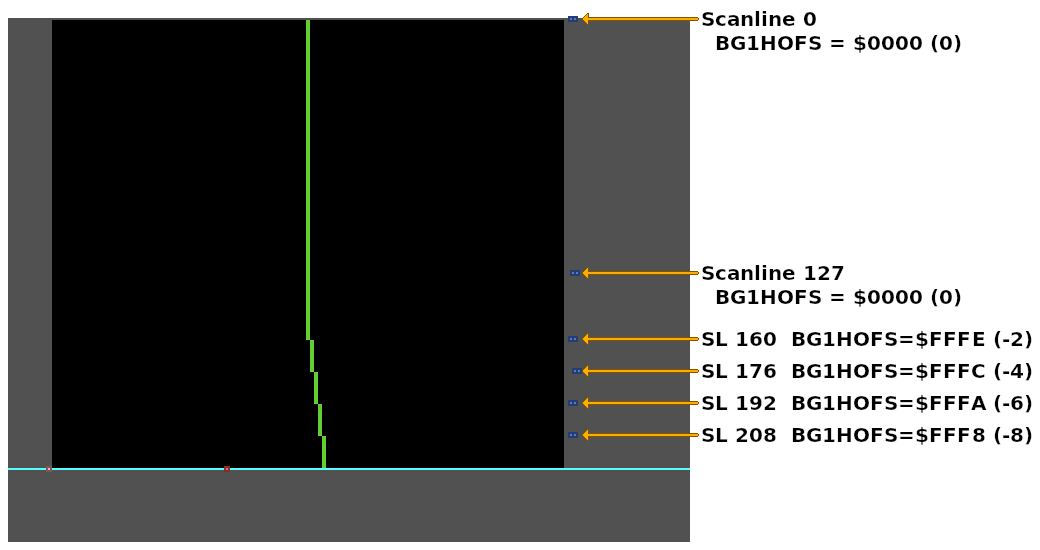
// HDMA Table for the `BG1HOFS` register (one register, write twice transfer pattern).
HdmaTable:
    // 160 scanlines with BG1HOFS = 0
    // Too many scanlines to fit in a single HDMA entry.
    db  127             // 127 scanlines, non-repeat entry
        dw  0

    db  33              // 33 scanlines, non-repeat entry (+127 = 160 scanlines total)
        dw  0           // Same data value as the previous entry


    // Change BG1HOFS every 16 scanlines
    db  16              // 16 scanlines, non-repeat entry
        dw  -2

    db  16              // 16 scanlines, non-repeat entry
        dw  -4

    db  16              // 16 scanlines, non-repeat entry
        dw  -6

    db  16              // 16 scanlines, non-repeat entry
        dw  -8

    db  0               // End HDMA table
Links
- HDMA Examples - by nesdoug
- Grog's Guide to DMA and HDMA on the SNES - superfamicom.org wiki

