Drawing window shapes
Combining two windows
A single window can only draw a monotone polygon. The S-PPU has 2 windows that can be combined using OR, AND, XOR or XNOR logic (as chosen by the WBGLOG and WOBJLOG registers) to form more complicated shapes. Additionally, each window can be inverted using the W12SEL, W34SEL and WOBJSEL registers.
There are three common methods of combining windows:
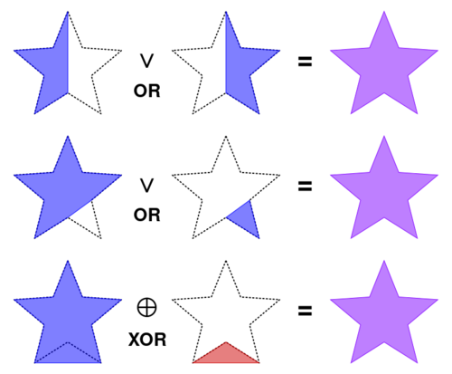
- Logical OR: One window holds the left side of the shape, the other window holds the right side of the shape.
- If a scanline segment is monotone, the segment can be drawn using a single window.
- The output is the union of both windows.
- Logical XOR: One window is the outline of the shape, the other window contains a cutout to remove.
- The output is the subtraction of the two windows if one window is completely contained within the other.
- Logical AND with an inverted window 2 (win AND (NOT win2))
- The output will subtract window 2 from window 1
For most shapes, using two HDMA channels to draw the two windows (in 2 registers write once mode) will consume less ROM space compared to drawing both windows with a single HDMA channel (in Four registers mode) as the two windows will typically have different heights.
The optimal window mask logic will depend on the shape being drawn.
The following diagram illustrates how a star can be drawn using OR or XOR logic. In this example, the XOR logic will require less space then the OR logic when using 2 HDMA channels as:
- The XOR example uses fewer scanlines then OR examples.
- The XOR example is horizontally symmetrical, which allows for further optimizations (see #Horizontally-symmetrical_window)
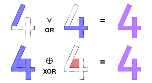
The following example draws a 4 digit using OR and XOR logic. If this 4 is drawn using two HDMA tables, the OR example will use less space despite it using more scanlines. Axis-aligned rectangles require fewer bytes compared to segments using slopes or curved edges.
In this OR example, the second window will require 5 HDMA non-repeat entries (16 bytes) to draw the three rectangle segments (assuming all segments are < 128 scanlines tall), compared to the multi-scanline repeat-mode HDMA entry (2n+1 bytes) required to draw the sloped second XOR window.
Drawing a single window with HDMA
A single window can be shaped using:
- One HDMA channel in 2 registers write once mode to
WH0andWH1. - Two HDMA channels in 1 register write once mode (ie, one channel to
WH0, the other toWH1).
The following considerations will need to be made when building a HDMA table for the window registers:
- A dynamic HDMA table must be double buffered to prevent glitches and/or screen tearing.
- HDMA table entries are a maximum 127 scanlines long. All segments/lines/shapes greater then 127 scanlines tall must be split into two. Alternatively, indirect HDMA can be used to map a contiguous buffer to two HDMA repeat mode entries.
- The left and right window positions must be clamped to an 8 bit value (0-255).
- The position must be 0 if the calculated value is < 0 (underflows).
- The position must be 255 if the calculated value is >= 256 (overflows).
- The code should detect if the window's scanline is horizontally offscreen. Failure to do so can result in a 1-pixel glitched window on the left or right side of the screen.
- The offscreen test is not required if every scanline of the window is guaranteed to be horizontally-onscreen (ie, a circle with a centre X-position between 0-255).
Windowless section
A window is considered empty (or offscreen) if the left position is greater than the right position. By creating a non-repeat HDMA table entry with a left position > 0 and a right position of 0, the window can be disabled for multiple scanlines. The HDMA table must end with an empty window if the window shape does not cover the entire display height.
Rectangles
The simplest HDMA window shape is a rectangle. It consists of four segments:
- An optional windowless section. This moves the rectangle downwards.
- An active window section. This sets the left and right window position to the left and right screen coordinates of the rectangle.
- Another windowless section, lasting a single scanline, ending the shape.
- An end of HDMA table byte.
All segments can be built using a non-repeating HDMA table entries.
Pseudo-code:
function hdma_rectangle_window(yPos, height, left, right) -> hdma_table:
    // INPUT: yPos   - the vertical offset (0 <= yPos <= 254)
    // INPUT: height - the height of the rectangle (1 <= height <= 254)
    // INPUT: left   - the left position of the rectangle (0 <= left <= 254)
    // INPUT: right  - the right position of the rectangle (left + 1 <= right <= 255)
    //
    // OUTPUT: A 2-registers-write-once HDMA table for the window position registers.

    hdma_table = next_hdma_buffer()

    buffer = hdma_table

    if yPos > 0:
        // Disable window for `yPos` scanlines
        buffer = non_repeating_entry(buffer, yPos, 255, 0)

    // Enable window
    buffer = non_repeating_entry(buffer, height, left, right)

    // Disable window
    buffer = non_repeating_entry(buffer, 1, 255, 0)

    // End HDMA table
    *buffer++ = 0

    return hdma_table


function non_repeating_entry(buffer, n, left, right) -> buffer:
    // Adds one or two HDMA entries to `buffer`, setting the `left` and `right` window position for `n` scanlines
    //
    // INPUT: buffer    - buffer to store the 2-registers-write-once HDMA table
    // INPUT: n         - number of scanlines (0 <= n <= 254)
    // INPUT: left      - window left position (0 <= left <= 255)
    // INPUT: right     - window right position (0 <= right <= 255)
    //
    // OUTPUT: buffer position after HDMA entries

    assert(n > 0)
    assert(n <= 127 * 2)

    if n <= 127:
        // One HDMA entry
        *buffer++ = n
        *buffer++ = left
        *buffer++ = right
    else:
        // Write two HDMA entries
        *buffer++ = 127
        *buffer++ = left
        *buffer++ = right

        *buffer++ = n - 127
        *buffer++ = left
        *buffer++ = right

    return buffer
Trapeziums
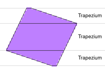
All straight lined single-window shapes can be built using one or more trapeziums.
There are multiple ways of drawing the sides of a trapezium:
- Bresenham's line drawing algorithm.
- Adding or subtracting an 8.8 fixed-point delta-X to the left/right position for every scanline. This is faster (but less accurate) then Bresenham's algorithm.
- Using separate code-paths for positive and negative delta-X values will simplify the 8-bit clipping code.
- Incrementing or decrementing an 8-bit position by a fixed value every scanline. This is the fastest method, but it can only be used to draw lines with fixed integer ratios.
- Alternatively, the window positions can be repeated every N scanlines to draw steep lines.
- Using a table of x-position deltas in ROM. For example; the delta-table for a 10 degree line is
[ 5, 6, 6 ]and the delta table for a 60 degree line is[ 1, 1, 0, 1, 0, 1, 0 ]. Delta-tables cannot be used to draw arbitrary lines.- It is recommended that delta-tables only contain unsigned numbers to avoid signed comparisons. Two drawing functions, one for incrementing X-positions and another for decrementing X-positions can halve the amount of ROM space required by taking advantage of line symmetry.
- Delta-tables are not limited to straight lines, they can also be used to draw curves and circles.
Unoptimised trapezium drawing pseudo-code (using the fixed-point delta-X method):
function draw_trapezium_window(buffer, height, left, left_dx, right, right_dx) -> left, right, buffer:
    // Builds a HDMA repeat-mode entry for a trapezium section.
    //
    // ASSUMES: left <= right
    //
    // INPUT: buffer    - buffer to store the 2-registers-write-once HDMA table
    // INPUT: height    - number of scanlines (1 <= height <= 127)
    // INPUT: left      - current left position (signed .8 fixed-point)
    // INPUT: dx_left   - delta-X for the left side of the window (signed .8 fixed-point)
    // INPUT: right     - current right position (signed .8 fixed-point)
    // INPUT: dx_right  - delta-X for the right side of the window (signed .8 fixed-point)

    // OUTPUT: new left position (signed .8 fixed-point integer)
    // OUTPUT: new right position (signed .8 fixed-point integer)
    // OUTPUT: buffer after entries

    assert(height > 0 and height <= 127)

    // Repeat mode, `height` scanlines
    *buffer++ = 0x80 | height

    repeat `height` times:
        left = left + dx_left
        right = right + dx_right

        // Test if the window is visible (assumes left <= right)
        if right < 0.0 or left >= 0x100.00:
            // Window is off-screen
            *buffer++ = 255
            *buffer++ = 0
        else:
            // Window is on-screen

            // clamp signed .8 fixed-point positions to 8 bit unsigned bytes
            l = left >> 8
            if l < 0:
                l = 0
            r = right >> 8
            if r > 255
                r = 255

            *buffer++ = l
            *buffer++ = r

    return left, right, buffer
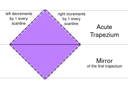
Acute Trapeziums
An acute trapezium offers a few advantages over an obtuse trapezium.
- The off-screen window test is not required if the short base of an acute trapezium is on-screen.
- If the short base is at the top, the left side is always moving left and the right side is always moving right, simplifying both the position calculation and the 8-bit clamping. Once a position has been clamped, all subsequent positions will remain 0 for the left and/or 255 for the right.
- If the short base is at the bottom, the acute trapezium can be built in reverse, bottom to top, to simplify the 8-bit clamping.
Examples
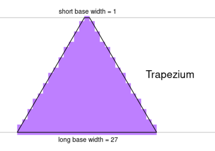
A triangle with a horizontal base can be created from a single acute trapezium with a very short base.
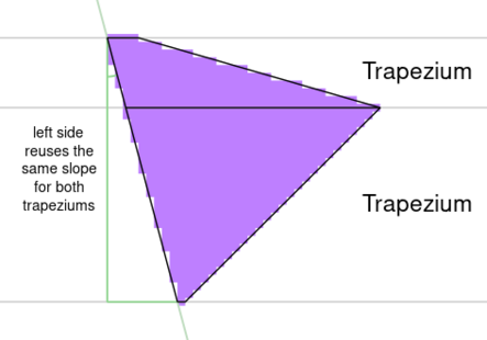
A triangle pointing right (centre_x > top_x) is made up of two trapeziums. The first trapezium has a short top base and bottom base of indeterminate width. The second trapezium immediately follows the first; with the left side's slope matching the first trapezium and the right side sloping at a different angle.
Triangles pointing left (centre_x < top_x) are a mirrored form of triangles pointing right.
Multiple trapeziums can be combined to create convex polygons.
Unrotated diamonds are built using two acute trapeziums. The second trapezium is vertical mirror of the first.
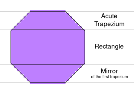
Unrotated Octagons are built using two acute trapeziums, separated by a rectangular section. The second trapezium is a vertical mirror of the first.
Translating precalculated windows
An alternative method of drawing window shapes involves precalculating the window's left and right position (from either code, an image file or handcrafted values) into a data table. A HDMA table is then built from the precalculated table. The window can be translated (moved) by adjusting the positions in the HDMA table as it being built.
This method can be both faster and simpler then building a non-precalculated HDMA table on the S-CPU, at the cost of extra ROM space.
The precalculated window can be translated vertically by either:
- Inserting a windowless-section at the start of the HDMA table to translate the window downwards.
- Skipping scanlines in the precalculated table to translate the window upwards.
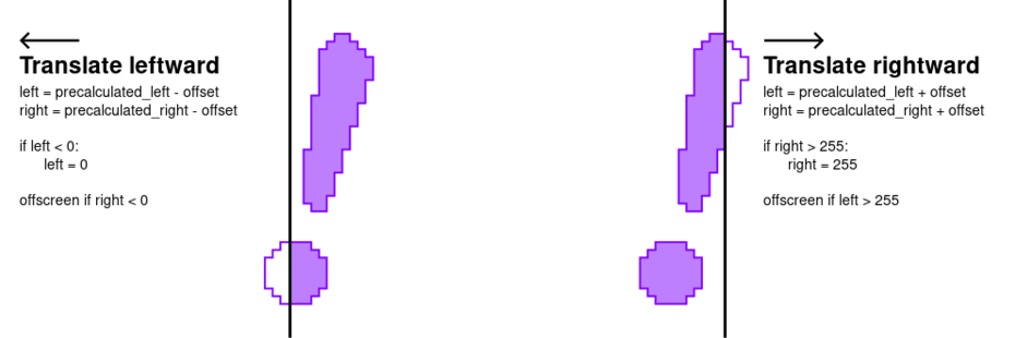
Horizontal translation is preformed by adding or removing an offset value to the window's left and right positions. A window offscreen test may be required. By splitting the code path in two, for leftwards and rightwards translation, all calculations can be preformed with an 8 bit Accumulator.
Horizontally-symmetrical window
If the window is horizontally-symmetrical, the precalculated table can be halved. By storing a single value per scanline, the horizontal distance from the centre (half-width), the left and right window positions can be calculated with a simple formula:
   left = xCenter - halfWidth
   right = xCenter + halfWidth
Followed by 8-bit clamping and an optional offscreen window test. By splitting the code path into three (xCenter < 0, 0 <= xCenter <= 255 and xCenter > 255), some tests can be skipped and all calculations can be preformed with an 8-bit unsigned Accumulator.
