HDMA examples: Difference between revisions
(Add two HDMA to CGRAM examples) |
(The HDMAEN writes in these examples must occur during VBlank.) |
||
| Line 89: | Line 89: | ||
// Enable HDMA channel 7 | // Enable HDMA channel 7 | ||
// (HDMAEN | // (This HDMAEN write must occur during VBlank, even if the screen is disabled) | ||
HDMAEN = 1 << 7 | HDMAEN = 1 << 7 | ||
</pre> | </pre> | ||
| Line 121: | Line 121: | ||
// Enable HDMA channel 7 | // Enable HDMA channel 7 | ||
// (HDMAEN | // (This HDMAEN write must occur during VBlank, even if the screen is disabled) | ||
HDMAEN = 1 << 7 | HDMAEN = 1 << 7 | ||
</pre> | </pre> | ||
| Line 169: | Line 169: | ||
// Enable HDMA channel 7 | // Enable HDMA channel 7 | ||
// (HDMAEN | // (This HDMAEN write must occur during VBlank, even if the screen is disabled) | ||
HDMAEN = 1 << 7 | HDMAEN = 1 << 7 | ||
</pre> | </pre> | ||
| Line 209: | Line 209: | ||
// Enable HDMA channel 7 | // Enable HDMA channel 7 | ||
// (HDMAEN | // (This HDMAEN write must occur during VBlank, even if the screen is disabled) | ||
HDMAEN = 1 << 7 | HDMAEN = 1 << 7 | ||
</pre> | </pre> | ||
| Line 250: | Line 250: | ||
// Enable HDMA channel 7 | // Enable HDMA channel 7 | ||
// (HDMAEN | // (This HDMAEN write must occur during VBlank, even if the screen is disabled) | ||
HDMAEN = 1 << 7 | HDMAEN = 1 << 7 | ||
</pre> | </pre> | ||
| Line 610: | Line 610: | ||
// Enable HDMA channels 6 & 7 | // Enable HDMA channels 6 & 7 | ||
// (HDMAEN | // (This HDMAEN write must occur during VBlank, even if the screen is disabled) | ||
HDMAEN = (1 << 6) | (1 << 7) | HDMAEN = (1 << 6) | (1 << 7) | ||
</pre> | </pre> | ||
| Line 667: | Line 667: | ||
// Enable HDMA channel 7 | // Enable HDMA channel 7 | ||
// (HDMAEN | // (This HDMAEN write must occur during VBlank, even if the screen is disabled) | ||
HDMAEN = 1 << 7 | HDMAEN = 1 << 7 | ||
</pre> | </pre> | ||
Revision as of 08:03, 28 May 2023
Examples for using HDMA.
Transfer patterns
The following is a suggested list of PPU registers that can be used in the various HDMA transfer patterns.
One register (DMAP pattern 0)
This pattern reads/writes a single byte to a single address on the B-bus (+0).
This pattern should not be used on write-twice or read-twice registers.
- BG Mode:
BGMODE - Mosaic Settings:
MOSAIC - BG Settings:
BG1SC,BG2SC,BG3SC,BG4SC,BG12NBA,BG34NBA - Mode 7 settings:
M7SEL - CGRAM address:
CGADD- A future HDMA channel should write to
CGDATAon the same scanline as theCGADDwrite.
- A future HDMA channel should write to
- Window settings:
W12SEL,W34SEL,WOBJSEL,WBGLOG,WOBJLOG - Layer enable:
TM,TS,TMW,TSW - Color math:
CGWSEL,CGADSUB - Screen Mode/Video Select:
SETINI - Fixed color data:
COLDATA- Only a single B/G/R channel can be changed in this pattern (unless multiple channels contain the same value). See
COLDATAfor more details.
- Only a single B/G/R channel can be changed in this pattern (unless multiple channels contain the same value). See
Two registers (DMAP pattern 1)
This pattern reads/writes two bytes to two addresses on the B-bus (+0, +1). It is useful when writing to two adjacent byte registers.
This pattern must not be used on write-twice or read-twice registers.
- Window 1 left and right position:
WH0&WH1 - Window 2 left and right position:
WH2&WH3 - Window mask settings:
W12SEL&W34SEL,W34SEL&WOBJSEL - Window mask logic:
WBGLOG&WOBJLOG - Layer Enable:
TM&TS,TMW&TSW - Color math settings:
CGWSEL&CGADSUB
One register, write twice (DMAP pattern 2)
This pattern reads/writes two bytes to a single write-twice or read-twice register on the B-bus (+0, +0).
- BG horizontal scroll offset:
BGnHOFS - BG vertical scroll offset:
BGnVOFS - Mode 7 matrix:
M7A,M7B,M7C,M7D,M7X,M7Y - CGRAM data:
CGDATA- Note: A previous HDMA channel should set the CGRAM address on the same scanline as a
CGDATAwrite
- Note: A previous HDMA channel should set the CGRAM address on the same scanline as a
- Fixed color data:
COLDATA- Only two of the three B/G/R channels can be changed in this pattern (unless two channels share the same value). See
COLDATAfor more details.
- Only two of the three B/G/R channels can be changed in this pattern (unless two channels share the same value). See
Two registers, write twice (DMAP pattern 3)
This pattern reads/writes four bytes to two adjacent write-twice or read-twice registers on the B-bus (+0, +0, +1, +1).
- BG scroll offsets:
BGnHOFS&BGnVOFS - 2 adjacent mode 7 matrix values:
M7A&M7B,M7C&M7D,M7X&M7Y - CGRAM address and data:
CGADD&CGDATA- This transfer will write two values to the CGRAM address, followed by a color word value to
CGDATA. - The first byte will be ignored by the PPU, the second byte contains the target CGRAM address (palette index), the third and forth bytes contain the color data.
- This transfer will write two values to the CGRAM address, followed by a color word value to
Four registers (DMAP pattern 4)
This pattern reads/writes four bytes to four addresses on the B-bus (+0, +1, +2, +3).
This pattern must not be used on write-twice or read-twice registers.
- All four window positions:
WH0&WH1&WH2&WH3
HDMA Tables
HDMA tables are made up of multiple HDMA entries. Each entry starts with a Line-Counter byte, followed by register data. The type of HDMA entry depends on the Line-Counter byte:
- Line-Counter 0: End of HDMA table. The HDMA channel will be deactivated and will remain deactivated until the start of the next frame (even if HDMAEN is written to mid-frame).
- Line-Counter 0x01-0x80: non-repeating HDMA entry. Writes once then waits LineCounter scanlines.
- Line-Counter 0x81-0xFF: repeating HDMA entry. Writes every scanline for the next LineCounter - 0x80 scanlines.
Non-repeat HDMA entries
A non-repeat HDMA entry (0x01 <= Line-Counter <= 0x80) is hdma_transfer_bytes + 1 bytes in size. It consists of the Line-Counter byte, followed by the data to transfer on the next Horizontal Blanking Period. Afterwards, the HDMA controller will wait for Line-Counter scanlines before processing the next HDMA entry.
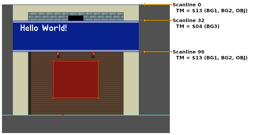
    DMAP7 = 0                   // one register, to PPU
    BBAD7 = .lobyte(TM)         // B-bus address
    A1T7  = .loword(HdmaTable)  // HDMA Table A-bus address
    B1B7  = .bankbyte(HdmaTable)

    // Enable HDMA channel 7
    // (This HDMAEN write must occur during VBlank, even if the screen is disabled)
    HDMAEN = 1 << 7
// HDMA Table targeting the `TM` register (One register transfer pattern).
HdmaTable:
    db  32              // 32 scanlines, non-repeat entry
        db  0x13        // TM = BG1, BG2, OBJ

    db  64              // 64 scanlines, non-repeat entry
        db  0x04        // TM = BG3

    db  1               // 1 scanline, non-repeat entry
        db  0x13        // TM = BG1, BG2, OBJ

    db  0               // End HDMA table
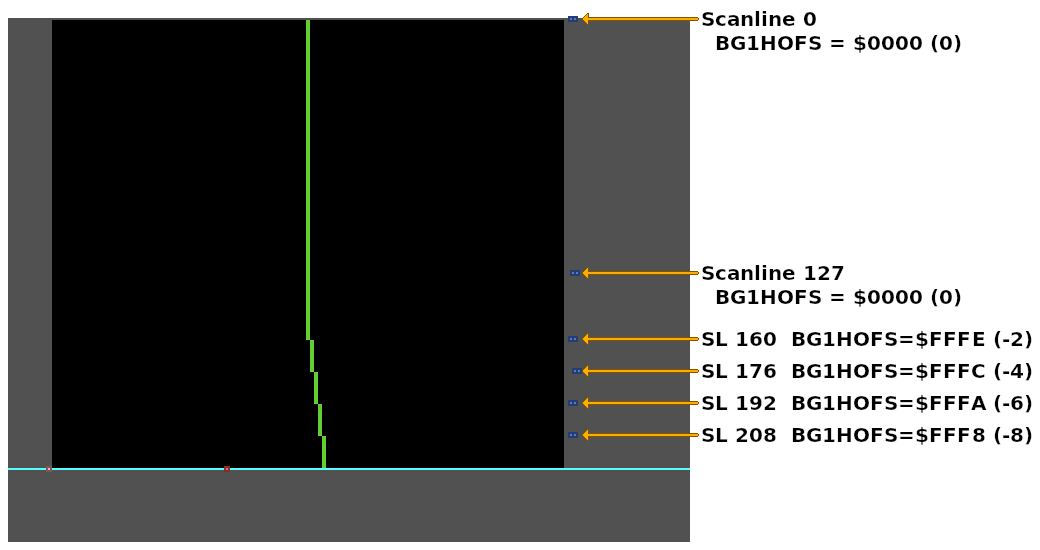
Each non-repeat HDMA entry is a maximum of 128 scanlines tall. Any HDMA entry with more then 128 scanlines must be split in two, with each entry containing the same data values.
    DMAP7 = 2                   // one write-twice register, to PPU
    BBAD7 = .lobyte(BG1HOFS)    // B-bus address
    A1T7  = .loword(HdmaTable)  // HDMA Table A-bus address
    B1B7  = .bankbyte(HdmaTable)

    // Enable HDMA channel 7
    // (This HDMAEN write must occur during VBlank, even if the screen is disabled)
    HDMAEN = 1 << 7
// HDMA Table for the `BG1HOFS` register (one register, write twice transfer pattern).
HdmaTable:
    // 160 scanlines with BG1HOFS = 0
    // Too many scanlines to fit in a single HDMA entry.
    db  127             // 127 scanlines, non-repeat entry
        dw  0

    db  33              // 33 scanlines, non-repeat entry (+127 = 160 scanlines total)
        dw  0           // Same data value as the previous entry


    // Change BG1HOFS every 16 scanlines
    db  16              // 16 scanlines, non-repeat entry
        dw  -2

    db  16              // 16 scanlines, non-repeat entry
        dw  -4

    db  16              // 16 scanlines, non-repeat entry
        dw  -6

    db  16              // 16 scanlines, non-repeat entry
        dw  -8

    db  0               // End HDMA table
Repeating HDMA entries
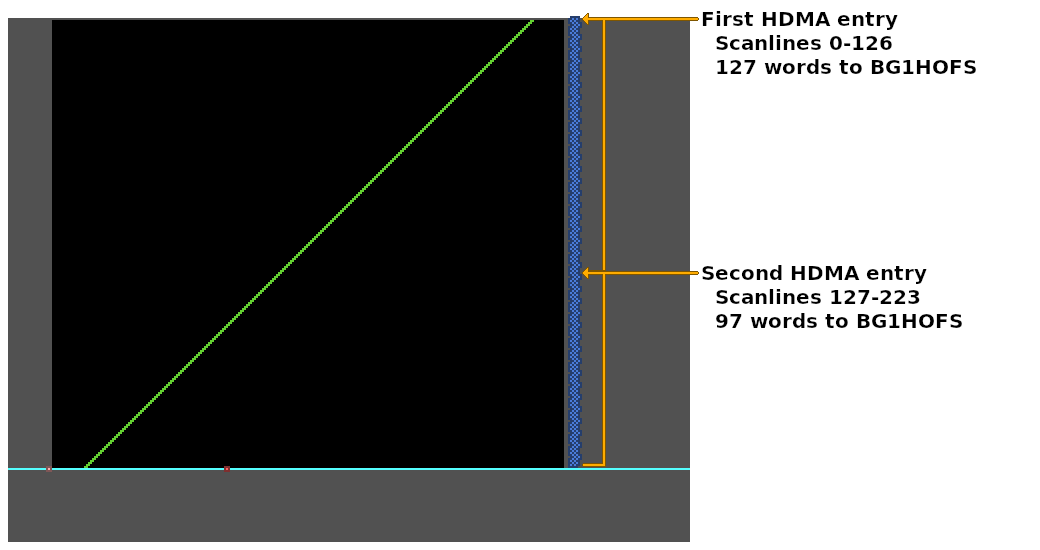
A repeating HDMA entry (Line-Counter >= 0x81) is hdma_transfer_bytes * (line_counter - 0x80) + 1 bytes in size. It consists of the Line-Counter byte, followed by count (line_counter - 0x80) values to transfer. For the next count scanlines, the HDMA controller will transfer hdma_transfer_bytes bytes of data during the next count Horizontal Blanking Periods.
Each repeating HDMA entry is a maximum of 127 scanlines tall. Any repeating HDMA entry with more than 127 scanlines must be split in two.
    DMAP7 = 2                   // one write-twice register, to PPU
    BBAD7 = .lobyte(BG1HOFS)    // B-bus address
    A1T7  = .loword(HdmaTable)  // HDMA Table A-bus address
    B1B7  = .bankbyte(HdmaTable)

    // Enable HDMA channel 7
    // (This HDMAEN write must occur during VBlank, even if the screen is disabled)
    HDMAEN = 1 << 7
// HDMA Table for the `BG1HOFS` register (one register, write twice transfer pattern).
HdmaTable:
    db  0x80 | 127      // 127 scanlines, repeat entry (maximum number of repeat scanlines per entry)
        // 127 words (254 bytes) of BG1HOFS data for the next 127 scanlines
        dw  144, 145, 146, 147, 148, 149, 150, 151, 152, 153, 154, 155, 156, 157, 158, 159, 160, 161, 162, 163, 164, 165, 166, 167, 168, 169, 170, 171, 172, 173, 174, 175, 176, 177, 178, 179, 180, 181, 182, 183, 184, 185, 186, 187, 188, 189, 190, 191, 192, 193, 194, 195, 196, 197, 198, 199, 200, 201, 202, 203, 204, 205, 206, 207, 208, 209, 210, 211, 212, 213, 214, 215, 216, 217, 218, 219, 220, 221, 222, 223, 224, 225, 226, 227, 228, 229, 230, 231, 232, 233, 234, 235, 236, 237, 238, 239, 240, 241, 242, 243, 244, 245, 246, 247, 248, 249, 250, 251, 252, 253, 254, 255, 256, 257, 258, 259, 260, 261, 262, 263, 264, 265, 266, 267, 268, 269, 270

    db  0x80 | 97       // 97 scanlines, repeat entry (+127 = 224 scanlines total)
        // 97 words (194 bytes) of BG1HOFS data for the next 97 scanlines
        dw  271, 272, 273, 274, 275, 276, 277, 278, 279, 280, 281, 282, 283, 284, 285, 286, 287, 288, 289, 290, 291, 292, 293, 294, 295, 296, 297, 298, 299, 300, 301, 302, 303, 304, 305, 306, 307, 308, 309, 310, 311, 312, 313, 314, 315, 316, 317, 318, 319, 320, 321, 322, 323, 324, 325, 326, 327, 328, 329, 330, 331, 332, 333, 334, 335, 336, 337, 338, 339, 340, 341, 342, 343, 344, 345, 346, 347, 348, 349, 350, 351, 352, 353, 354, 355, 356, 357, 358, 359, 360, 361, 362, 363, 364, 365, 366, 367

    db  0               // End HDMA table
Indirect HDMA
All HDMA entries in HDMA indirect mode (bit 6 of DMAPn set) are 3 bytes in size. They consist of the Line-Counter byte followed by a word address. This word address is combined with the DASBn (Indirect HDMA Bank) register and points to the data to transfer to/from the B-bus.
The format and behaviour of the Line-Counter byte is the same as the HDMA direct addressing mode.
Indirect mode can be used to map an unbroken contiguous array of 224 register values to two HDMA repeat entries.
    DMAP7 = 0x42                        // Indirect mode, one write-twice register, to PPU
    BBAD7 = .lobyte(BG1HOFS)            // B-bus address
    A1T7  = .loword(IndirectHdmaTable)  // HDMA Table A-bus address
    B1B7  = .bankbyte(IndirectHdmaTable)

    DASB7 = .bankbyte(ContiguousArray)  // Indirect HDMA bank

    // Enable HDMA channel 7
    // (This HDMAEN write must occur during VBlank, even if the screen is disabled)
    HDMAEN = 1 << 7
// Contiguous array of `BG1HOFS` values for all 244 scanlines.
// 224 words (448 bytes)
ContiguousArray:
    dw  367, 366, 365, 364, 363, 362, 361, 360, 359, 358, 357, 356, 355, 354, 353, 352, 351, 350, 349, 348, 347, 346, 345, 344, 343, 342, 341, 340, 339, 338, 337, 336, 335, 334, 333, 332, 331, 330, 329, 328, 327, 326, 325, 324, 323, 322, 321, 320, 319, 318, 317, 316, 315, 314, 313, 312, 311, 310, 309, 308, 307, 306, 305, 304, 303, 302, 301, 300, 299, 298, 297, 296, 295, 294, 293, 292, 291, 290, 289, 288, 287, 286, 285, 284, 283, 282, 281, 280, 279, 278, 277, 276, 275, 274, 273, 272, 271, 270, 269, 268, 267, 266, 265, 264, 263, 262, 261, 260, 259, 258, 257, 256, 255, 254, 253, 252, 251, 250, 249, 248, 247, 246, 245, 244, 243, 242, 241, 240, 239, 238, 237, 236, 235, 234, 233, 232, 231, 230, 229, 228, 227, 226, 225, 224, 223, 222, 221, 220, 219, 218, 217, 216, 215, 214, 213, 212, 211, 210, 209, 208, 207, 206, 205, 204, 203, 202, 201, 200, 199, 198, 197, 196, 195, 194, 193, 192, 191, 190, 189, 188, 187, 186, 185, 184, 183, 182, 181, 180, 179, 178, 177, 176, 175, 174, 173, 172, 171, 170, 169, 168, 167, 166, 165, 164, 163, 162, 161, 160, 159, 158, 157, 156, 155, 154, 153, 152, 151, 150, 149, 148, 147, 146, 145, 144


// Indirect HDMA Table for the `BG1HOFS` register (one register, write twice transfer pattern).
IndirectHdmaTable:
    // Cannot fit all 224 scanlines in a single HDMA entry.
    // Splitting the table into two equally sized entries.
    db  0x80 | 112      // 112 scanlines, repeat entry
        // Word address pointing to the first half of ContiguousArray
        dw  ContiguousArray

    db  0x80 | 112      // 112 scanlines, repeat entry (+112 = 224 scanlines total)
        // Word address pointing to the second half of ContiguousArray
        dw  ContiguousArray + 112 * 2

    db  0               // End HDMA table
Indirect mode can also be used to map the same contiguous array multiple times, creating a repeating HDMA effect.
    DMAP7 = 0x42                        // Indirect mode, one write-twice register, to PPU
    BBAD7 = .lobyte(BG1HOFS)            // B-bus address
    A1T7  = .loword(IndirectHdmaTable)  // HDMA Table A-bus address
    B1B7  = .bankbyte(IndirectHdmaTable)

    DASB7 = .bankbyte(SineTable)        // Indirect HDMA bank

    // Enable HDMA channel 7
    // (This HDMAEN write must occur during VBlank, even if the screen is disabled)
    HDMAEN = 1 << 7
// Array of `BG1HOFS` values for every scanline
// 48 words (96 bytes)
SineTable:
    // Sine wave, calculated using python:
    // >>> import math
    // >>> [ round(16.5 * math.sin(math.radians(i * 360 / 48))) for i in range(48) ]
    dw  0, 2, 4, 6, 8, 10, 12, 13, 14, 15, 16, 16, 16, 16, 16, 15, 14, 13, 12, 10, 8, 6, 4, 2, 0, -2, -4, -6, -8, -10, -12, -13, -14, -15, -16, -16, -16, -16, -16, -15, -14, -13, -12, -10, -8, -6, -4, -2


// Indirect HDMA Table for the `BG1HOFS` register (one register, write twice transfer pattern).
IndirectHdmaTable:
    db  0x80 | 48       // 48 scanlines, repeat
        // Word address to BG1HOFS data
        dw  SineTable

    db  0x80 | 48       // 48 scanlines, repeat
        dw  SineTable

    db  0x80 | 48       // 48 scanlines, repeat
        dw  SineTable

    db  0x80 | 48       // 48 scanlines, repeat
        dw  SineTable

    db  0x80 | 48       // 48 scanlines, repeat
        dw  SineTable

    db  0               // End HDMA table
                        // Not required.  HDMA ends at the Vertical Blanking Period.
Dynamic HDMA tables
To prevent screen tearing or glitches, dynamic HDMA effects must not modify the HDMA registers or HDMA tables while they are in use. This can be achieved by either:
- Precalculating the HDMA tables (stored in ROM or decompressed/calculated into RAM) and changing the HDMA table address (A1Tn / A1Bn) to the next HDMA table during VBlank.
- Modifying the HDMA tables inside the VBlank routine.
- Double buffering the HDMA table.
Modifying HDMA tables during VBlank
Since the HDMA controller is deactivated during the Vertical Blanking Period, it is safe to write to a HDMA table in RAM inside the VBlank routine. If the changes to the table are minor, this can be easier and faster then a double-buffed HDMA table.
This technique is useful for adjusting the scanline height of HDMA entries over time.
When the screen is active, ensure the HDMA table and HDMA registers are only modified during VBlank to prevent screen tearing and glitches.
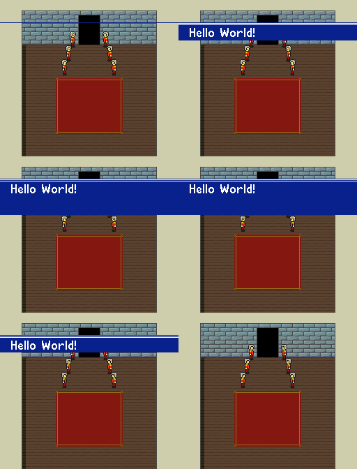
The following example takes the HDMA table from the textbox example above and modifies the Line-Counter byte of the second HDMA entry to create a textbox wipe animation. When textboxHeight is 0, only the first HDMA entry is processed and the textbox will not be visible. When textboxHeight is between 1-128, the second and third HDMA entries will be processed, and the textbox will be onscreen for textboxHeight scanlines.
Variables:
    hdmaBuffer      u8[64] - Buffer to store HDMA table
    textboxHeight   u8     - Visible textbox height, in scanlines.  MUST BE <= 128.
    state           enum   - The current state of the textbox wipe animation


// TIMING: Force-Blank, HDMA disabled
subroutine SetupHdma_TextboxWipeAnimation:
    memcopy(HdmaTable, hdmaBuffer)
    textboxHeight = 0

    // Setup Hdma registers
    DMAP7 = 0                       // one register, to PPU
    BBAD7 = .lobyte(TM)             // B-bus address
    A1T7  = .loword(hdmaBuffer)     // HDMA Table A-bus address
    B1B7  = .bankbyte(hdmaBuffer)


// TIMING: Screen active, in VBlank
subroutine VBlank_TextboxWipeAnimation:
    // Modify HDMA table.
    // Set the height of the second HDMA entry
    hdmaBuffer[2] = textboxHeight

    // Enable HDMA channel 7
    HDMAEN = 1 << 7


// Called once per frame in the MainLoop
subroutine Process_TextboxWipeAnimation:
    if state == OPEN_TEXTBOX:
        textboxHeight = min(textboxHeight + 1, 64)
    else if state == CLOSE_TEXTBOX:
        textboxHeight = max(textboxHeight - 1, 0)


// HDMA Table for the `TM` register (one register transfer pattern).
HdmaTable:
    db  32              // 32 scanlines, non-repeat entry
        db  0x13        // TM = BG1, BG2, OBJ

    db  64              // 64 scanlines, non-repeat entry  (This is the byte that is modified by VBlank_TextboxWipeAnimation)
        db  0x04        // TM = BG3

    db  1               // 1 scanline, non-repeat entry
        db  0x13        // TM = BG1, BG2, OBJ

    db  0               // End HDMA table
Double buffered HDMA tables
Double buffering is required to build a HDMA table in the MainLoop (outside the VBlank routine) without any screen tearing or glitches. One buffer will be used by the HDMA controller to display the HDMA effect, while the other buffer can be safely written to by the MainLoop. After the MainLoop has built the HDMA, the VBlank routine will swap the buffer used by the HDMA controller.
The example below creates a simple horizontal offset parallax effect on a single background layer. This example ensures the HDMA controller never reads a dirty buffer by:
- Building the first HDMA table during Force-Blank setup, while HDMA is disabled.
- Never enabling or disabling a HDMA effect while the screen is active.
- Trusting the VBlank routine is never executed during a lag frame.
- In this example; if the VBlank routine is executed during a lag frame, the HDMA controller and the MainLoop could be accessing the same buffer at the same time.
- See VBlank_interrupts for an example of a VBlank routine with lag-frame detection.
Variables:
    hdmaBufferA         u8[512] - first HDMA buffer
    hdmaBufferB         u8[512] - second HDMA buffer

    activeHdmaBuffer    u8      - Flag to determine which buffer to write to

    cameraX             u16     - Camera's X position


// TIMING: Force-Blank, HDMA disabled
// Uses HDMA channel 7
subroutine Setup:
    assert .bankbyte(hdmaBufferA) == .bankbyte(hdmaBufferB)

    DMAP7 = 2                       // one write-twice register, to PPU
    BBAD7 = .lobyte(BG1HOFS)        // B-bus address
    B1B7  = .bankbyte(hdmaBufferA)  // HDMA Table A-bus bank

    // HDMA Table address is written during VBlank

    // The hdmaBuffer must be populated before the next VBlank routine
    BuildHdmaTable()


// TIMING: Screen active, in VBlank
// TIMING: MUST NOT be executed in a lag frame
// Uses HDMA channel 7
subroutine VBlank:
    // Set HDMA table word address (depending on which buffer was last used by the MainLoop)
    if activeHdmaBuffer == 0:
        A1T7 = .loword(hdmaBufferB)
    else:
        A1T7 = .loword(hdmaBufferA)

    // Enable HDMA channel 7
    HDMAEN = 1 << 7


// TIMING: MUST NOT be called more than once per frame
function GetNextHdmaBuffer() -> *u8
    if activeHdmaBuffer == 0:
        activeHdmaBuffer = 1
        return &hdmaBufferA
    else:
        activeHdmaBuffer = 0
        return &hdmaBufferB


// TIMING: MUST NOT be called more than once per frame
subroutine BuildHdmaTable:
    buffer = GetNextHdmaBuffer()

    // Four non-repeat HDMA entries
    // Remember, all `u8` writes MUST be <= 128

    buffer[ 0] as u8  = 45
    buffer[ 1] as u16 = cameraX >> 3

    buffer[ 3] as u8  = 22
    buffer[ 4] as u16 = cameraX >> 2

    buffer[ 6] as u8  = 128
    buffer[ 7] as u16 = cameraX

    buffer[ 9] as u8  = 128
    buffer[10] as u16 = cameraX << 1

    // End HDMA table
    buffer[12] as u8  = 0
Double buffering in indirect mode
When double-buffering in HDMA indirect mode; the HDMA table can be stored in ROM, while the buffers (two contiguous scanline arrays) are located in RAM.
The following example creates a simple shear animation by modifying the horizontal-scroll register every scanline. It has the same design considerations and limitations as the previous example.
Constants:
    N_SCANLINES = 224

Variables:
    scanlineArray_A         u16[N_SCANLINES] - first buffer
    scanlineArray_B         u16[N_SCANLINES] - second buffer

    activeScanlineArray     u8               - flag to determine which scanlineArray to write to (in lowram)

    animationTimer          u16              - animation timer for the HDMA effect


// TIMING: Force-Blank, HDMA disabled
// Uses HDMA channel 7
subroutine Setup:
    assert .bankbyte(HdmaTable_A) == .bankbyte(HdmaTable_B)
    assert .bankbyte(scanlineArray_A) == .bankbyte(scanlineArray_B)

    DMAP7 = 0x42                        // Indirect mode, one write-twice register, to PPU
    BBAD7 = .lobyte(BG1HOFS)            // B-bus address
    B1B7  = .bankbyte(HdmaTable_A)      // HDMA Table bank byte
    DASB7 = .bankbyte(scanlineArray_A)  // Indirect HDMA bank

    // HDMA Table address is written during VBlank


    animationTimer = 0

    // The scanlineArray must be populated before the next VBlank routine
    ProcessShearAnimation()


// TIMING: Screen active, in VBlank
// TIMING: MUST NOT be executed in a lag frame
// Uses HDMA channel 7
subroutine VBlank:
    // Set HDMA table word address (depending on which buffer was last used by the MainLoop)
    if activeScanlineArray == 0:
        A1T7 = .loword(HdmaTable_B)
    else:
        A1T7 = .loword(HdmaTable_A)

    // Enable HDMA channel 7
    HDMAEN = 1 << 7


// TIMING: MUST NOT be called more than once per frame
function GetNextScanlineArray() -> *u16
    if activeScanlineArray == 0:
        activeScanlineArray = 1
        return &hdmaBufferA
    else:
        activeScanlineArray = 0
        return &hdmaBufferB


// Called once per frame in the MainLoop
subroutine ProcessShearAnimation:
    scanlineArray = GetNextScanlineArray()

    animationTimer = animationTimer + 2
    if animationTimer > 512 + N_HDMA_SCANLINES:
        animationTimer = 512 + N_HDMA_SCANLINES

    // tmp is a signed s16 variable
    tmp = animationTimer

    for i = 0 to N_HDMA_SCANLINES-1:
        tmp = tmp - 2
        scanlineArray[i] = clamp(tmp, 0, 256)


// Indirect HDMA table to the data in `scanlineArray_A`
// NOTE: This table can only be used on 2-byte HDMA transfer patterns
HdmaTable_A:
    db  0x80 | 112      // 112 scanlines, repeat entry
        // Word address pointing to the first half of `scanlineArray_A`
        dw  scanlineArray_A

    db  0x80 | 112      // 112 scanlines, repeat entry
        // Word address pointing to the second half of `scanlineArray_A`
        dw  scanlineArray_A + 112 * 2

    db  0               // End HDMA table


// Indirect HDMA table to the data in `scanlineArray_B`
// NOTE: This table can only be used on 2-byte HDMA transfer patterns
HdmaTable_B:
    db  0x80 | 112      // 112 scanlines, repeat entry
        // Word address pointing to the first half of `scanlineArray_B`
        dw  scanlineArray_B

    db  0x80 | 112      // 112 scanlines, repeat entry
        // Word address pointing to the second half of `scanlineArray_B`
        dw  scanlineArray_B + 112 * 2

    db  0               // End HDMA table
Other Examples
HDMA to CGRAM
Before any HDMA writes to CGDATA (CGRAM data write) are preformed, the CGADD CGRAM word address (color index) must be set on the same scanline as the CGDATA write.
One method involves two HDMA channels:
- A one register HDMA to CGADD to set the CGRAM color index.
- A one register, write twice HDMA to CGDATA on next HDMA channel to write the CGRAM color data.
Both HDMA tables should use the same Line-Counter values in all HDMA entries to ensure both CGADD and CGDATA writes occur on the same scanline.
The CGDATA register should always be written using the One register, write twice or Two registers, write twice HDMA patterns.
Additional HDMA channels to CGDATA can be used to change multiple sequential CGRAM colors per scanline.
    // HDMA channel 6 to CGADD (set the CGRAM color index)
    DMAP6 = 0                           // one register, to PPU
    BBAD6 = .lobyte(CGADD)              // B-bus address
    A1T6  = .loword(CGADD_HdmaTable)    // HDMA Table A-bus address
    B1B6  = .bankbyte(CGADD_HdmaTable)

    // HDMA channel 7 to CGDATA (write the color data)
    DMAP7 = 2                           // one write-twice register, to PPU
    BBAD7 = .lobyte(CGDATA)             // B-bus address
    A1T7  = .loword(CGDATA_HdmaTable)   // HDMA Table A-bus address
    B1B7  = .bankbyte(CGDATA_HdmaTable)

    // Enable HDMA channels 6 & 7
    // (This HDMAEN write must occur during VBlank, even if the screen is disabled)
    HDMAEN = (1 << 6) | (1 << 7)
// HDMA Table to CGADD (byte register pattern)
CGADD_HdmaTable:
    db  32                              // 32 scanlines, non-repeat entry
        db  COLOR_TO_CHANGE

    .repeat 28, i                       // This HDMA entry is repeated 28 times:
        db  2                               // 6 scanlines, non-repeat entry
            db  COLOR_TO_CHANGE
    .endrepeat

    db  0                               // end of HDMA table


// HDMA Table to CGDATA (write twice pattern)
//
// This HDMA table MUST be processed after `CGADD_HdmaTable`.
//
// The HDMA entries MUST have the same line-count as `CGADD_HdmaTable`.
//
CGDATA_HdmaTable:
    db  32                              // 32 scanlines, non-repeat entry
        dw  0

    .repeat 28, i                       // This HDMA entry is repeated 28 times:
        db  2                               // 2 scanlines, non-repeat entry
            dw  (28 - i) << 10
    .endrepeat

    db  0                               // end of HDMA table
Alternatively, both CGADD and CGDATA writes can be preformed with a single HDMA channel using the two registers, write twice HDMA transfer pattern to CGADD/CGDATA.
Each HDMA transfer will write 4 bytes to the PPU:
- A dummy write to CGADD.
- A CGRAM word address (color index) write to CGADD.
- The low-byte of the color data to CGDATA.
- The high-byte of the color data to CGDATA.
    // HDMA channel 7 to CGADD & CGDATA
    DMAP7 = 3                           // two registers write-twice, to PPU
    BBAD7 = .lobyte(CGADD)              // B-bus address
    A1T7  = .loword(HdmaTable)          // HDMA Table A-bus address
    B1B7  = .bankbyte(HdmaTable)

    // Enable HDMA channel 7
    // (This HDMAEN write must occur during VBlank, even if the screen is disabled)
    HDMAEN = 1 << 7
// HDMA Table to CGADD & CGDATA (two registers, write twice pattern)
HdmaTable:
    db  32                              // 32 scanlines, non-repeat entry
        db  0, COLOR_TO_CHANGE              // two writes to CGADD
        dw  0                               // CGDATA data (color value)

    .repeat 28, i                       // This HDMA entry is repeated 28 times:
        db  2                               // 2 scanlines, non-repeat entry
            db  0, COLOR_TO_CHANGE              // two writes to CGADD
            dw  (28 - i) << 10                  // CGDATA data (color value)
    .endrepeat

    db  0                               // end of HDMA table
Links
- HDMA Examples - by nesdoug
- Grog's Guide to DMA and HDMA on the SNES - superfamicom.org wiki
